
This post introduces a custom C++ library to control the popular Dynamixel XL 320 servo directly with a Raspberry Pi 4, without the need for an additional controller/shield like the OpenCM board. You'll just need a level shifter to drive the motor and LED and an additional logic gates IC in case you want to read the servo's output, but these are cheap and popular electronic components. The Rasberry configuration and wiring are included, with everything you need to have a working setup rapidly.
Before we just start ...
The Dynamixel XL 320 is a cheap and powerful servomotor that is used in various robotics project like the Metabot or the Robotis Mini. In this tutorial we are going to control a single servo, but the same hardware and software can be used to control up to 253 servos simply by chaining them up. You'll need the following elements:
- A XL 320 servo, obviously.
- A Rasberry Pi 4 model 4B, with an OS installed (e.g. Raspberry Pi OS x64) and access to a terminal.
- A level shifter to convert 3.3V to 5V. I used the bi-directional level converter from Sparkfun.
- A power supply that can deliver 7.4V to power up the servo. Scale the delivered Amps to the number of servos chained up.
- A breadboard and some jumper wires.
- Optionnally, a SN74LS241N to be able to read the servo's output.
Configuring the Raspberry
Let's assume you have a fresh install of the Raspberry Pi OS (x64 version) with access to a terminal (e.g. via ssh). First you have to choose one of the serial ports for your project, since the Raspberry Pi 4 has 6 of them:
| Port | TxD | RxD | CTS | RTS |
|---|---|---|---|---|
| UART 0 | GPIO 14 | GPIO 15 | - | - |
| UART 1 | GPIO 14 | GPIO 15 | - | - |
| UART 2 | GPIO 0 | GPIO 1 | GPIO 2 | GPIO 3 |
| UART 3 | GPIO 4 | GPIO 5 | GPIO 6 | GPIO 7 |
| UART 4 | GPIO 8 | GPIO 9 | GPIO 10 | GPIO 11 |
| UART 5 | GPIO 12 | GPIO 13 | GPIO 14 | GPIO 15 |
Given that UART 0 and 1 are both connected to the same GPIO you can only use one of them and there are potentially only 5 accessible UARTs at any one time, which is already a lot. UART2 is not always usable since GPIO 0-1 are usually used for I²C. In this tutorial we are going to use the UART3 serial port, but you can easily translate it to your needs. We won't need the CTS/RTS lines, but for the read/write operation we will need an extra
We have to enable the UART 3 port and to make it run at 1MHz, as this is the default (factory setting) baud rate of the XL 320. Let's edit the main configuration file:
sudo nano /boot/config.txt then add:
dtoverlay=uart3
init_uart_clock=16000000
and reboot. To check that the serial port is successfully set up, you can try:
snake@raspberrypi:~ $ ls /dev/ttyA*
/dev/ttyAMA0  /dev/ttyAMA1
Installing the library
First download or clone the following Github repository:
https://github.com/CandelierLab/XL_320
and install it on your Raspberry. For an easy compilation I use Codelite, which you can access remotely in graphical mode via ssh by using the
me@local:~$ ssh -X user@IP.of.my.pi and then, in the Raspberry terminal:
sudo apt-get update
sudo apt-get install codelite libwxgtk3.0-gtk3-dev
codelite &
When codelite is installed you just have to open a blank project, add the 3 downloaded files and then build and run.
Et voilà, you are now ready for the software part.
Wiring
The simpler case: just drive that servo !
In case you just want to drive the motor and LED, and not read any output from it, then you just need a PSU delivering 7.4V to power the servo and a level shifter to convert the 3.3V logic of the Raspberry into the 5V logic required by the servo, like the bi-directional level converter from Sparkfun. Here is a scheme of this first wiring:
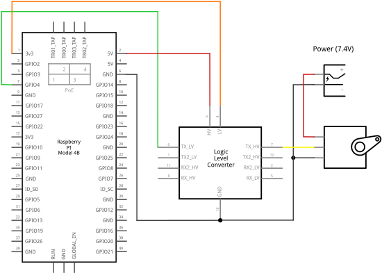
and here is the corresponding breadboard view:
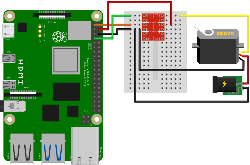
As you can see, only the
The complete setup: get the readout for extra info
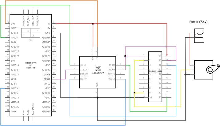
Want the full monty? Then you'll have to add a few logic gates to convert the two lines of the serial port into the single Data line of the servo, as explained in the XL 320 official documentation. They recommend to use either a 74LVC2G241 or a NC7WZ241 dual buffer, but those components are usually sold in tiny SMT packages that are extremely difficult to solder if you don't do your own PCB with at least a reflux setup. So I opted for a SN74LS241N that has similar functions in a through-hole package that can be easily mounted over a breadboard.
Here is the scheme of the complete wiring:
and the corresponding breadboard view:
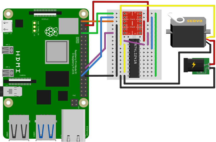
Note that we now have the
Using the library
The library comes with a sample main file that summarizes the main steps:
#include "XL_320.hpp"

using namespace std;

int main(int argc, char **argv)
{

    XL_320 Servo;
    Servo.verbose = true;

    // --- Timing optimization

    /*
     * Do this only once per Servo, the result is stored in the EEPROM
     */

    // Servo.setTorqueEnable(0);
    // Servo.setReturnDelayTime(100);
    // Servo.setStatusReturnLevel(1);
    // Servo.setTorqueEnable(0);

    // --- Commands

    // Test ping
    Servo.ping();

    // Test LED colors
    for (int i=0; i<8; i++) {
        Servo.setLED(i);
        usleep(1000000);
    }

    return 0;
}
Including the header file
Note that there are two instructions that have to be run once for the first time use, or after each factory reset:
Servo.setReturnDelayTime(100);
Servo.setStatusReturnLevel(1);
The first one is to allow enough time between write and read calls, and the second disables the output apart from methods using
Last but not least: when the
→ |    Header   | ID | Size  | In |  CRC  |
  | FF FF FD 00 | 01 | 03 00 | 01 | 19 4E |

Read 14 bytes.
← |    Header   | ID | Size  | In | Er | Param    |  CRC  |
  | FF FF FD 00 | 01 | 07 00 | 55 | 00 | 5E 01 1E | 15 47 |
Result: 5E 01 1E
Model 350 (30)
Have fun !
Comments
No comments on this post so far.

Leave a comment